


AC Box for Solar PV Systems – AC Connection Boxes up to 630 A
Project-Specific AC Connection Solutions for Commercial and Industrial PV Systems – Compliant with EN 61439.
On this page
Product Overview and Applications
Project-Specific AC Connection Solutions for Commercial and Industrial PV Systems
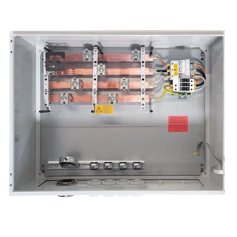
The Q3 AC Box combines the AC outputs of PV inverters and provides a connection to the downstream low-voltage distribution system. Depending on project requirements, we integrate NH fuse-switch disconnectors, busbar systems, surge protection and the necessary connection components.
Available in ratings from 160 A to 630 A – designed, manufactured and tested in Germany.
AC Box for Solar PV – Safe Grid Feed-In
The Q3 AC Box provides a safe, standards-compliant connection between PV inverters and the grid connection point or transformer.
As a high-performance AC connection box, it provides the following functions:
Consolidation of high AC currents
Integration of NH load break switches
Overcurrent protection and selectivity
Surge protection Type 1+2 (optionally expandable)
Standards-compliant PEN separation for TN-C / TN-C-S
Designed for Commercial and Industrial PV Systems
Q3 AC Boxes at a Glance
| Application | Commercial and industrial PV systems, large rooftop installations and high-capacity inverter systems |
| Function | Combining and protecting the AC outputs of PV inverters |
| Rated Current | 160 A, 250 A, 400 A or 630 A |
| Earthing Arrangements | TN-C and TN-C-S |
| Busbar System | Copper, sized to suit project requirements |
| Switching and Protection Equipment | NH fuse-switch disconnectors, upstream fuse protection and a project-specific selectivity concept |
| Surge protection | Available for project-specific integration, e.g. Type 1+2 SPDs or extended protection arrangements |
| Enclosure / degree of protection | IP66, suitable for indoor and sheltered outdoor applications |
| Applicable standards | EN 61439 |
| Design and Configuration | Project-specific design based on rated current, earthing arrangement, short-circuit withstand capability, selectivity and distribution network operator requirements |

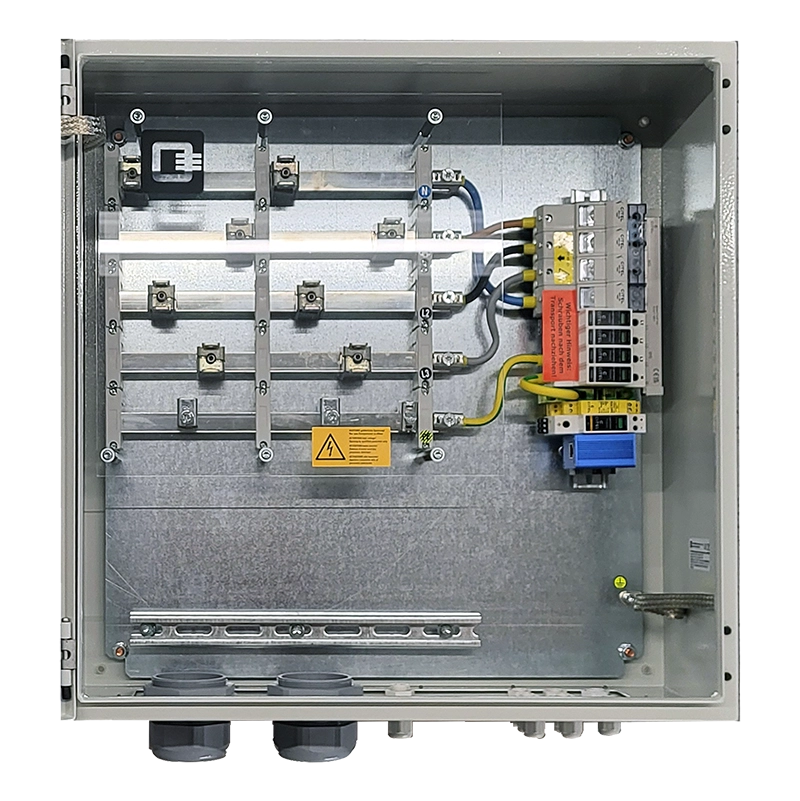
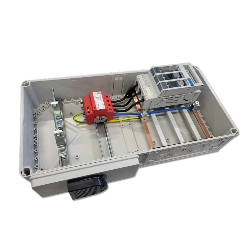
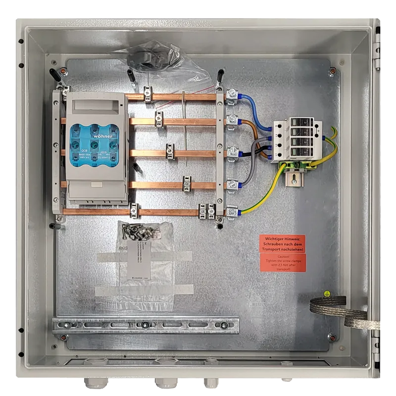

AC Box Variants from 160 A to 630 A
| AC Box 160 A | Compact AC connection solution for lower-capacity PV systems, providing a standards-compliant connection to the low-voltage network. |
| AC Box 250 A | High-performance AC connection box for commercial PV projects, with project-specific upstream fuse protection and selectivity coordination. |
| AC Box 400 A | Robust AC distribution assembly for combining high AC currents in industrial photovoltaic installations. |
| AC Box 630 A | High-current AC connection box for industrial grid connection points, featuring NH fuse-switch disconnectors and optional integrated surge protection. |
| Project-Specific Configuration | Busbar dimensions, NH fuse size, SPD configuration and cable entries are adapted to the requirements of each project. |
| Other Configurations | Custom configurations available on request |
The application examples are provided for guidance only. Actual suitability depends on the electrical design and operating conditions.
Key Technical Specifications at a Glance
| Rated Current Options | 160 A / 250 A / 400 A / 630 A |
| Earthing Arrangements | TN-C / TN-C-S |
| Busbar System | Copper, sized to suit project requirements |
| Switching Devices | NH Fuse-Switch Disconnectors |
| Surge protection | Available for project-specific integration |
| PEN Disconnection Point | Tool-operated arrangement, where specified |
| Enclosure | IP66 |
| Applicable standards | EN 61439 |
| Manufacturing | Germany |
Switching and Protection Equipment in the Q3 AC Box
The technical configuration is tailored to the requirements of each project. Switching devices, protective components and current-carrying systems are selected to suit the specific electrical operating conditions.

Busbars and Protection Against Direct Contact
The busbar system is fitted with a transparent protective cover to prevent accidental contact with live parts. The cover also allows visual inspection of the components.
NH Fuse-Switch Disconnectors
Integrated NH fuse-switch disconnectors provide safe isolation of the AC side. The configuration is determined according to the project’s rated current and short-circuit requirements.
Surge protection
Optional or integrated Type 1+2+3 surge protective devices (SPDs) to protect inverters and downstream equipment.
Enclosure and Degree of Protection
The AC Box is available with an IP66-rated enclosure, suitable for indoor and outdoor installation.
Q3. The Box Makers.
Earthing Arrangements and Connection Design
AC Boxes for TN-C and TN-C-S Systems
The Q3 AC Box can be designed for different grid connection arrangements. The design takes account of the earthing arrangement, neutral and protective conductor configuration, and the required switching and protection functions.
TN-C
An earthing arrangement in which the protective earth and neutral functions are combined in a single PEN conductor within the relevant section of the electrical installation.
TN-C-S
An earthing arrangement in which the combined PEN conductor is separated into individual protective earth (PE) and neutral (N) conductors at the designated point.
For further information on the differences between TN-C, TN-S and TN-C-S earthing arrangements, please refer to BauNetz Wissen – Netzsysteme.
Depending on the earthing arrangement, the PEN disconnection point, surge protection and connection components are configured in accordance with the applicable technical and standards requirements.

Project-Specific Design
From Connection Design to the Finished AC Box

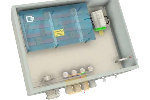
Customised AC Connection Boxes Instead of Standard Solutions
Every PV installation has different requirements for AC-side distribution. This is why each Q3 AC Box is tailored to the electrical conditions and connection design of the individual project.
Our design process takes the following factors into account:
- Number, type and rated AC currents of the inverters
- Network type and earthing concept
- Rated current and required short-circuit withstand capability
- Upstream fuse protection and selectivity requirements
- Surge protection concept
- Conductor cross-sections, cable entries and strain relief
- Installation location and environmental conditions
- Technical connection requirements of the distribution network operator (DNO)
Design, Manufacturing and Testing
AC Boxes – Designed and Manufactured in Germany
Q3 AC Boxes are designed and manufactured in Germany. Design, manufacturing and testing are carried out in accordance with the applicable requirements of the EN 61439 series of standards.
Each project-specific configuration includes the appropriate product identification and the required technical documentation.
Project-Specific Labelling
CE conformity
Documentation according to EN 61439
Q3. The Box Makers.
Frequently Asked Questions About AC Connection Boxes
When Is an AC Connection Box Used in a PV System?
An AC connection box is used to combine the AC outputs of one or more photovoltaic inverters and connect them to the downstream low-voltage distribution system. Depending on the system design, it also provides switching, isolation and protection functions. The Q3 AC Box is designed specifically for commercial and industrial PV installations.
Which AC Rated Currents Are Available?
The Q3 AC Box is available in rated current options of 160 A, 250 A, 400 A and 630 A. Other configurations are available on request. The appropriate variant is selected based on inverter capacity, earthing arrangement, short-circuit conditions and the electrical requirements of the project.
Can the AC Box Be Designed for TN-C and TN-C-S Systems?
Yes. The Q3 AC Box can be designed for TN-C and TN-C-S earthing arrangements. The design takes account of the relevant earthing system, PEN conductor configuration and any required separation into neutral (N) and protective earth (PE) conductors. The PEN disconnection point and connection components are configured according to the project’s earthing and protection concept.
Which Surge Protective Devices Can Be Integrated?
Surge protective devices (SPDs), such as Type 1+2+3 devices, can be integrated into the Q3 AC Box according to project requirements. Other configurations are possible depending on the earthing arrangement and protection concept. Device selection and rating take account of the electrical requirements and intended installation conditions.
What Information Is Required to Design an AC Connection Box?
To design an AC connection box for your project, we require details such as inverter type and quantity, rated AC current, earthing arrangement, short-circuit conditions, upstream protection, conductor cross-sections and installation location. Existing circuit diagrams, protection concepts and the distribution network operator’s technical connection requirements help us determine the appropriate configuration.
What Technical Documentation Is Provided with the AC Box?
Technical datasheets and project-specific documentation are available for the Q3 AC Box. Depending on the configuration, the documentation may include circuit diagrams, technical specifications for the low-voltage switchgear and controlgear assembly, and the required test and conformity documentation in accordance with the applicable requirements of EN 61439.
AC Connection Box Project Request
Project-specific design of AC connection boxes for grid connection, feed-in points, and storage solutions.

Technical Documentation AC Box

Data sheets, circuit diagrams, certificates, and technical documentation for AC distribution and transfer points.

Products AC Boxes

Overview of standardized and customized AC boxes for various grid types and power ranges.

Q3 DC Connection Technology

Complementary DC generator junction boxes and string boxes for a coordinated complete system