


AC Connection Box for PV Systems
Technical Aspects, Structure, and Standards-Compliant Design
AC Connection Boxes are used for the safe grid connection, distribution, and protection of AC circuits in photovoltaic systems – from the inverter to the grid connection point.
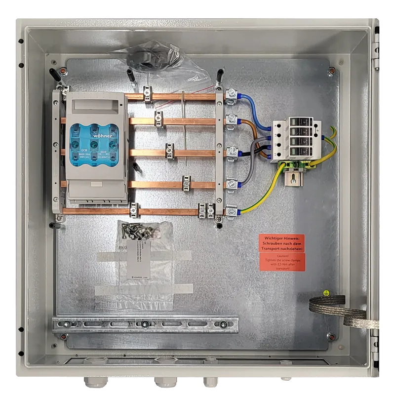
What is an AC Connection Box?
An AC Connection Box forms the defined interface between the inverter and the low-voltage grid or building installation. It combines protection, switching, and distribution functions in a standards-compliant switchgear assembly according to EN 61439.
In contrast to DC connection technology on the generator side, the AC box handles the grid-side integration of the PV system. It ensures that current, voltage, and the protection concept are correctly adapted to the existing infrastructure.

Typical Applications
AC Connection Boxes are particularly used in:
Commercial and industrial
PV systems
Storage integration
on the AC side
Central
inverter concepts
Defined grid connection points
according to VDE specifications
Multiple inverters
with common grid feed-in
They can be designed as pure feed-in boxes, as collection boxes for multiple inverters, or as transfer points to the main distribution board.
Secure Connection between Inverter and Grid
In photovoltaic systems, AC Connection Boxes perform the central task of connecting inverters safely, in compliance with standards, and in a maintenance-friendly manner to the low-voltage grid, the grid transfer point, or the transformer. They bundle high AC currents, integrate protection and switching devices, and create a clear, defined interface between generation and the grid.
Q3 ENERGIE‘s AC connection technology is designed for use in commercial, industrial, and grid-connected PV applications and is planned, constructed, and tested as a low-voltage switchgear assembly according to EN 61439.

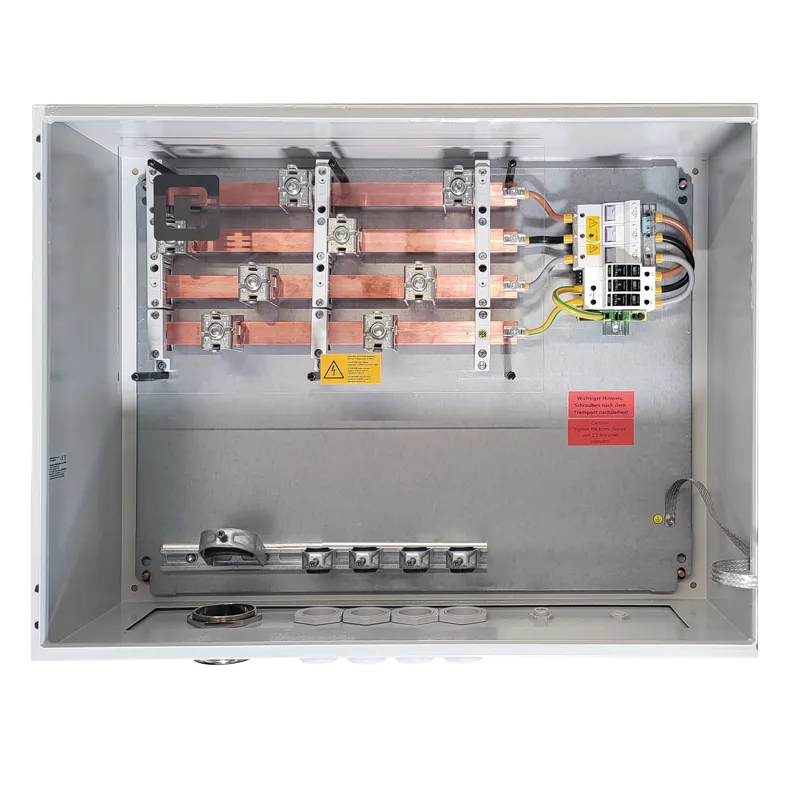
Functions of an AC Connection Box in a PV System
AC Connection Boxes fulfill several safety- and operation-relevant functions within the PV system:
They do not replace a building’s sub-distribution, but rather form a powerful interface specifically designed for PV applications between generation and the grid connection point.
Structure of an AC Connection Box
The specific structure is project-specific; typical components include:
The design is implemented as a low-voltage switchgear assembly according to EN 61439-1 / -2.
Technical Design Criteria
The dimensioning of an AC Connection Box depends on:
Rated current of the inverter
or feed-in power
Grid type
(TN-S, TN-C, TT)
Short-circuit power at the grid connection point
Selectivity to upstream protective devices
Rated voltage
(e.g., 400 V AC)
Thermal load capacity of the busbars
Correct design considers both continuous current and potential short-circuit currents and their breaking capacity.
Grid Types and Protection Concepts
The design of the AC Connection Box largely depends on the existing grid type:
The protection concept defines:
Especially for systems with high feed-in power, considering short-circuit withstand capability is mandatory.
Surge Protection on the AC Side
On the AC side, overvoltages arise, among other things, from:
Q3 AC Connection Boxes can be equipped with surge protective devices of types 1+2 or 1+2+3. Integration is close to the current path and coordinated with the respective grid type. Remote signaling contacts for status monitoring can be optionally integrated.
Normative Requirements
For AC Connection Boxes, the following apply in particular:
Compliance with these standards ensures electrical safety and conformity with applicable technical regulations.
Standardized or System-Specific Solution?
AC Connection Boxes can be manufactured as standardized variants or project-specifically.
For customized designs, the following are adapted:
to the respective project requirement.

How a Q3 AC Connection Box is Created
Each Q3 AC Connection Box is designed and manufactured based on project-specific requirements.
After checking the electrical characteristics – especially rated current, short-circuit power, grid type, and protection concept – the technical dimensioning of the following takes place:
■ Busbars and conductor cross-sections
■ Switching and protective devices
■ Surge protection
■ Enclosure size and degree of protection
The design is carried out according to EN 61439 as a tested low-voltage switchgear assembly.
Both thermal load capacity and selectivity, as well as mechanical requirements, are taken into account.
This results in an AC Connection Box that is not only standards-compliant but also precisely tailored to the respective system structure.
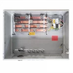
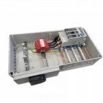
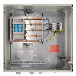
1. Mechanische Basis und Montageplatte
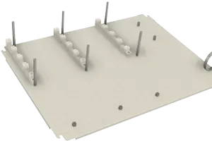
Stable mounting plate with defined fastening, insulation, and grounding points as a basis for busbars, terminals, and switchgear.
2. Aufbau des Sammelschienensystems
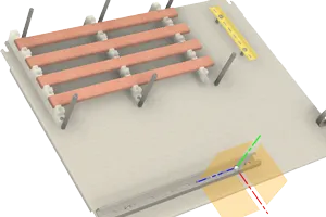
Installation and dimensioning of solid copper busbars according to rated current, grid type, and short-circuit withstand capability.
3. Anschlussklemmen und Leistungsabgänge
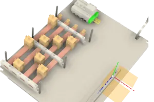
Integration of high-performance connection terminals for preparing inverter and transformer connections for large conductor cross-sections.
4. Integration von Schutz‑ und Schaltgeräten
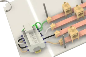
Integration of NH load disconnectors and surge protective devices directly in the defined current path.
5. Berührschutz und Sicherheit
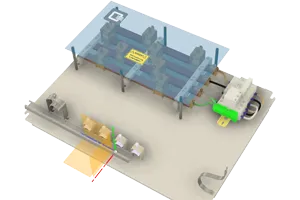
Covering active parts with transparent protective covers according to IP2X/IPXXB for safe operation and maintenance.
6. Kabeleinführung und Zugentlastung
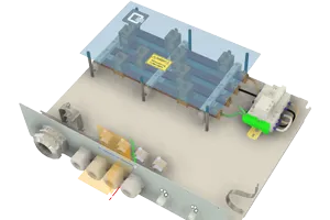
Preparation of cable entries with suitable glands and mechanical strain relief.
7. Integration ins Gehäuse
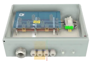
Installation of the equipped mounting plate into the IP66 enclosure for indoor or outdoor use, including door grounding.
8. Prüfung und Dokumentation
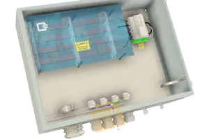
Routine test according to EN 61439, labeling, and complete technical documentation.
Distinction from DC Connection Technology
While DC connection boxes relate to the string level of the PV generator, AC connection technology operates on the AC side after the inverter. Accordingly, the following differ:
Both systems complement each other and together form a safe overall system.
Project Inquiry AC Connection Box
Would you like to design an AC Connection Box project-specifically, have technical details checked, or select the appropriate configuration for your photovoltaic or storage system?
The following inquiry form allows us to record all relevant project data in a structured and traceable manner.
You are welcome to send circuit diagrams, grid specifications, protection concepts, or other technical documents directly. Based on this, we will check the electrical framework conditions, dimension busbars, protective devices, and connection points, and design the AC box to suit your project.

Project Inquiry AC Connection Box

Project-specific design of AC connection boxes for grid connection, feed-in points, and storage solutions.

Technical Documents AC Box

Datasheets, circuit diagrams, certificates, and technical documentation for AC distributions and transfer points.

AC Connection Technology Products

Overview of standardized and customized AC boxes for various grid types and power ranges.

Q3 DC Connection Technology

Complementary DC generator junction boxes and string boxes for a coordinated overall system