


QFire Firefighter Safety Switch for 954 PV Strings
Planning PV Firefighter Safety Switches for Large PV Systems
Large rooftop PV systems place particular demands on DC-side shutdown technology. PV firefighter safety switches for large PV systems must reliably integrate numerous strings, widely distributed generator fields and long cable routes into a coordinated shutdown concept.
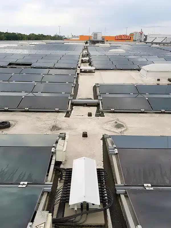
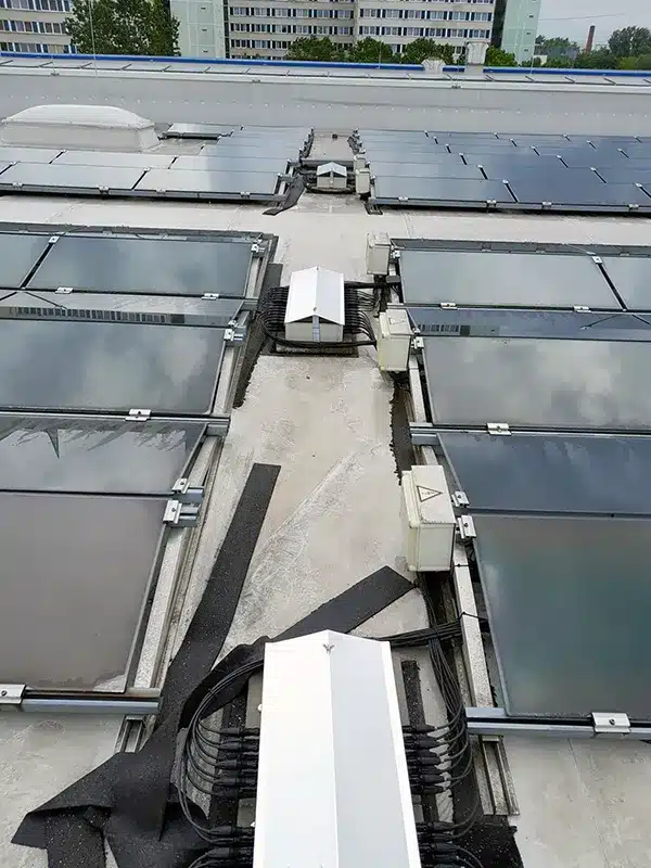
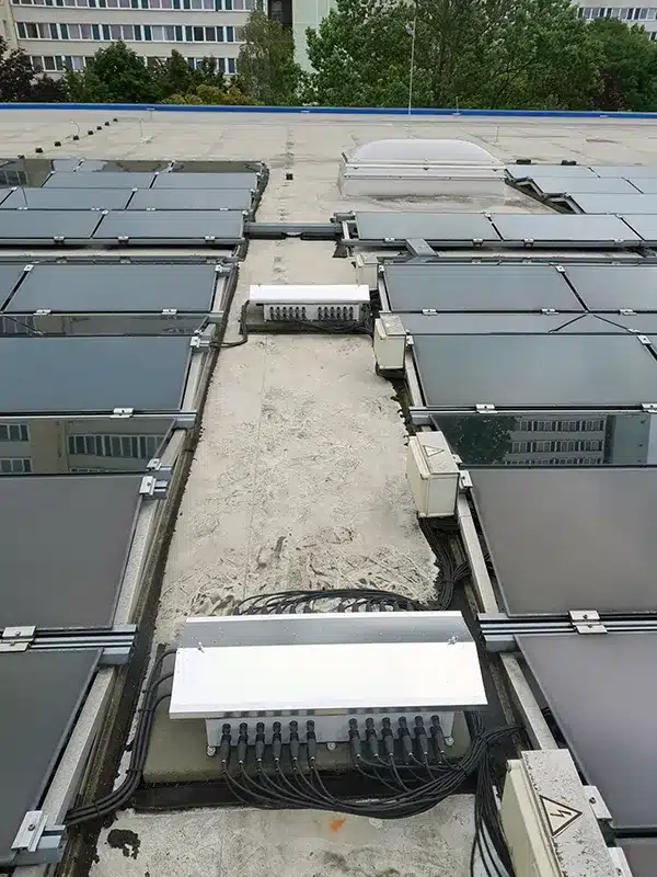
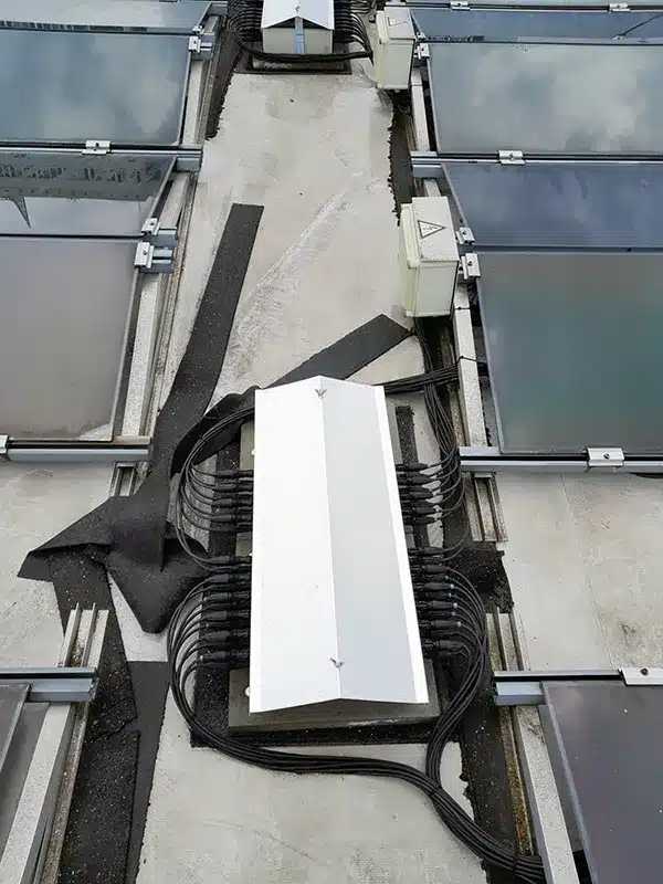
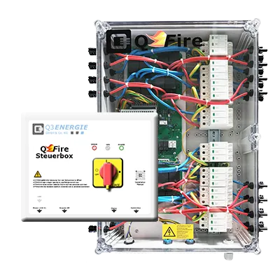
For this large-scale PV installation, seven QFire Control Boxes and a total of 84 QFire BIG Switch Boxes were installed. In total, the system enables two-pole disconnection of 954 PV strings from the inverter side. The Switch Boxes are distributed across the roof close to the individual generator fields.
For reliable long-term operation, the QFire Switch Boxes were additionally fitted with purpose-built protective canopies. These reduce direct exposure to sunlight and precipitation and demonstrate how sound planning, professional installation and responsible system operation work together.
Expertly implemented by HVT Elektro GmbH! ⚡☀️

Planning
Large PV System
Firefighter Switch
| Project data | |
|---|---|
| Application | Large commercial rooftop PV system |
| Location | Berlin-Lichtenberg, Berlin |
| Technology | QFire BIG PV Firefighter Safety Switch for Large PV Systems |
| Control Boxes | 7 |
| Switch Boxes | 84 |
| PV Strings | 954 |
| Electrical Contractor | HVT Elektro GmbH |
| Planning | TÜV SÜD Advimo GmbH |
| Special Feature | Purpose-built sun and weather protection for reliable long-term operation |
On this page
Firefighter Safety Switch for Large PV Systems: Commercial Rooftop
For a large commercial rooftop PV installation in Berlin, an extensive QFire system comprising seven Control Boxes and a total of 84 QFire BIG Switch Boxes was implemented. The system integrates 954 PV strings into a coordinated DC shutdown concept.
The installation illustrates the requirements that need to be considered when planning PV firefighter safety switches for large PV systems – including string allocation, shutdown architecture, mounting locations and reliable long-term operation.
Generator-Side Disconnection of the PV Strings
The Switch Boxes are positioned so that, in the event of shutdown, the DC cables between QFire and the inverter are disconnected from the generator side. Before any work is carried out on the installation, the absence of voltage must be properly verified by a qualified electrician. The cable section between the PV modules and the respective Switch Box remains energised by the PV modules.
Particularly on large roof areas, positioning the Switch Boxes close to the PV generator reduces the length of DC cabling that remains energised after shutdown. Mounting positions, cable routes and building entry points therefore need to be considered together at an early stage of system planning.
84 QFire Switch Boxes for 954 PV Strings
The QFire system configured for this large PV installation comprises seven Control Boxes and a total of 84 QFire BIG Switch Boxes. Of these, 27 Switch Boxes were configured for ten PV strings each and 57 Switch Boxes for twelve PV strings each.
This allows a total of 954 PV strings to be integrated into the shutdown concept. The large number of Switch Boxes demonstrates how the modular QFire architecture can be adapted to extensive rooftop PV systems, multiple generator fields and different string configurations.
Project-Specific Design Rather Than an Off-the-Shelf Solution
When designing PV firefighter safety switches for large PV systems, considering only the total number of PV strings is not sufficient. The assignment of strings to inverters and MPP trackers, the distribution of the generator fields, cable routes and the required shutdown groups are equally important.
The QFire Switch Boxes were therefore configured to suit the existing system design. Different Switch Box sizes allowed the individual string groups to be accommodated without specifying unnecessarily large enclosures or additional connection boxes.
Planning the Shutdown Architecture for Large Rooftop PV Systems
In a PV installation of this scale, a firefighter safety switch is not an isolated standalone device. It forms part of an overall shutdown, cable-routing and fire safety concept.
The number of PV strings is only the starting point. A technically robust system design must also take into account the spatial distribution of the generator fields, the inverter architecture, MPP trackers, cable routes and the required triggering points.
The earlier the shutdown architecture is incorporated into the PV system design, the better the Switch Boxes, Control Boxes and cable routes can be coordinated. If shutdown points are defined only at a later stage, this can result in unnecessarily long DC cable routes, difficult-to-access mounting locations or additional modifications to the existing system architecture.
String Layout, MPP Trackers and Inverters Must Be Considered Together
Each PV string must remain clearly assigned to its corresponding inverter and MPP tracker within the shutdown system. Spare connections within a Switch Box are therefore not sufficient reason to combine strings with different electrical assignments.
In addition to the number of strings, the design requires information such as open-circuit voltage, maximum short-circuit current, number of modules per string and assignment to the inverter inputs. A layout of the generator fields, the planned building entry points and the routing of the DC cables are equally important.
Based on this information, the required number of Switch Boxes, the appropriate number of strings per box and the optimum installation positions can be determined. This ensures that the electrical system architecture remains clearly traceable throughout the firefighter switch system.
Clearly Define Shutdown Groups and Triggering Points
On extensive rooftop PV installations, not all Switch Boxes necessarily need to form one single shutdown group. Depending on the building layout, inverter architecture or fire safety concept, it may be appropriate to create several separate system areas.
For each shutdown group, the assigned PV strings, Switch Boxes and inverters should be documented. The central triggering point, any external emergency-stop or key switches, and the required system behaviour in the event of a supply failure must also be defined.
The functional description should additionally specify how the system is returned to operation after a shutdown. This is particularly important where external triggering devices, a fire alarm system or higher-level control systems are integrated into the shutdown concept.
Distinguishing Operating Status from Fault Indication
A status contact does not automatically indicate every possible fault within the system. Depending on the system configuration, it may, for example, only indicate whether the QFire system is switched on or off.
If the signal is to be evaluated by a building management system, PV monitoring system or fire alarm system, the required information must be defined during the planning stage. Operating status, shutdown indication and technical fault indication are separate functions.
Possible feedback signals may relate to the operating state, a fault in the control connection, the status of a shutdown group or the condition of an integrated surge protection device. The exact meaning of each contact should therefore be clearly specified in the tender documentation, functional description and circuit diagram.
Weather-Protected Installation of QFire Switch Boxes
Electrical switching and control equipment installed on flat roofs is exposed to demanding environmental conditions. In addition to rain, snow and ice, direct solar radiation, significant temperature fluctuations, contamination and possible condensation can affect enclosures, connectors and installed components.
The QFire installation requirements therefore specify a protected mounting location. The equipment should not be directly exposed to weather, should be protected against direct sunlight and should preferably be installed in a shaded location.
A High IP Rating Does Not Replace a Suitable Mounting Location
The IP rating describes the protection provided by an enclosure against contact, foreign objects and water under defined test conditions. However, it does not provide a complete assessment of all thermal, climatic and mechanical loads present at the actual installation location.
Read more
Even with a high IP rating, direct solar radiation, internal enclosure temperature, condensation, standing water and mechanical loading of cables and connectors must therefore be assessed separately.
It is equally important that enclosure covers, closures and seals remain correctly closed. Even a partially open enclosure can compromise the intended level of protection.
Direct Solar Radiation Increases Thermal Load
The temperature inside an enclosure installed on an unshaded flat roof does not necessarily correspond to the measured ambient air temperature. Direct solar radiation can heat the enclosure surface and subsequently increase the internal temperature.
Read more
In addition to this solar heating, losses generated by the installed components must also be taken into account. PCBs, relays, power supplies, connection points and, where applicable, integrated surge protection devices must remain within the permissible operating conditions specified for the respective configuration.
Persistently elevated temperatures can accelerate the ageing of electronic components, seals and insulating materials. Shading a Switch Box is therefore not merely a visual consideration, but an important contribution to reliable long-term operation.
Purpose-Built Sun and Weather Protection by HVT Elektro
For the QFire Switch Boxes on this large PV installation, HVT Elektro implemented site-specific protective canopies. The light-coloured covers reduce direct solar radiation on the enclosures while also providing additional protection against direct precipitation.
Read more
The canopies were designed so that the string connectors and cable routing at the sides remain accessible. The enclosure covers can also be reached for inspection, maintenance and service.
Purpose-built weather protection should not sit tightly against the enclosure. Sufficient clearance should remain between the Switch Box and the protective canopy to allow air circulation and avoid additional heat accumulation. Drainage, secure fixing and permanent maintenance access must also be ensured.
Electrical Contractor, Planner and Manufacturer Working Together
Large PV installations are operated for many years. During this period, technical modifications, maintenance work or additional protective measures may become necessary. The quality of a project therefore becomes apparent not only during initial installation, but also throughout subsequent operation.
A reliable long-term solution is achieved when the planner, electrical contractor and manufacturer combine their respective expertise. The planner defines the shutdown and interface functions, the electrical contractor implements the installation on site, and the manufacturer provides product expertise, technical requirements and service support.
Practical Implementation by HVT Elektro
HVT Elektro adapted the protective canopies to the existing mounting positions, cable routes and Switch Boxes. The existing string cabling and arrangement of the shutdown equipment could therefore be retained.
The solution combines shading, weather protection and maintenance access. It demonstrates how an electrical contractor can implement site-specific technical optimisation even on an existing PV installation.
Technical Support by Q3 ENERGIE
Q3 ENERGIE supports QFire projects beyond the design and manufacturing stages. Manufacturer support also includes assessing installation conditions, assisting with troubleshooting and coordinating suitable measures with the specialist contractors involved.
For a sound technical assessment, overview photographs of the mounting location, detailed images of the Switch Boxes and Control Boxes, information on solar exposure and weather protection, and the assignment of the affected strings and inverters are particularly useful.
Experience gained from real installations is incorporated into technical documentation, training and the ongoing development of the QFire system. Manufacturer support therefore does not end with the delivery of the Switch Boxes.
Q3. The Box Makers.
Planning Guidance for PV Firefighter Safety Switches on Flat Roofs
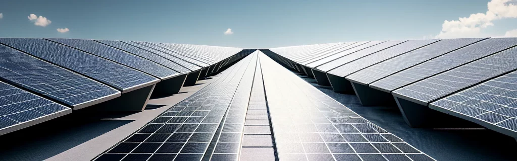
The mounting location of a PV firefighter safety switch for large PV systems should be defined during the detailed design stage. This allows cable routing, fixing, weather protection and maintenance access to be considered together from the outset.
Selecting the mounting position only after arriving on site often results in compromises. Typical consequences include unnecessarily long cable routes, difficult-to-access enclosures or inadequate options for permanent shading.
Check the Mounting Location Before Installation
Before approving the mounting location, it should be verified whether the Switch Box can be positioned as close as practicable to the PV generator or in the area of the building entry point. At the same time, the location must be protected against direct solar radiation and direct exposure to weather.
Adequate air circulation, controlled drainage and permanently secure fixing must also be ensured. Enclosure covers, closures, connectors, labels and status indicators must remain fully accessible after installation.
Cables must not be subjected to mechanical tension or routed with excessively tight bending radii. Additional rooftop equipment or subsequent maintenance work must not obstruct access to the Switch Boxes.
Document the Final Installation Condition During Commissioning
In addition to electrical testing, commissioning should include documentation of the final installation condition. Photographs facilitate future operation and maintenance and make it easier to identify changes to the mounting environment.
The positions of the Switch Boxes and Control Boxes, string assignments, cable routing, fixing arrangements and the existing sun and weather protection should be documented.
The specified triggering points and feedback signals must also be tested. Shutdown functions, status contacts and any available fault indications should be tested and recorded in accordance with the functional description.
Maintenance and Regular Functional Testing
A DC disconnection device must remain fully functional throughout its operating life. An annual functional test is therefore specified for the QFire system.
The shutdown should be initiated using the final intended triggering point within the control chain. Where, for example, an external key switch forms part of the shutdown concept, this device must also be included in the functional test.
It must then be verified that the DC cables between the QFire Switch Box and the inverter have been disconnected from the generator side. Before any work is carried out on electrical equipment, the absence of voltage must be properly verified by a qualified electrician.
Check More Than the Switching Function
In addition to the electrical shutdown function, the installation conditions should also be inspected during maintenance. This includes the condition of the protective canopies, secure fixing and the integrity of enclosures, covers and closures.
Cables, connectors and drainage paths should also be checked. Moisture, condensation, contamination or mechanical loading can indicate unsuitable operating conditions.
Where surge protection is integrated, its condition and any associated remote signalling should also be checked.
Take Changes at the Mounting Location Into Account
PV rooftops can change during the lifetime of an installation. New cabling, additional technical equipment, roof membrane work or subsequently installed structures can alter the original installation conditions.
During every maintenance inspection, it should therefore be checked whether shading remains effective, whether any new heat source has been installed nearby and whether maintenance access remains unobstructed.
Protective canopies can also become loose or displaced as a result of wind, snow or work carried out on the roof. Such changes should be identified and rectified before they affect the operation or accessibility of the switching equipment.
Frequently Asked Questions About Firefighter Safety Switches for Large PV Systems
Why Are QFire Switch Boxes Installed Decentrally on the Roof?
On large rooftop PV installations, generator fields are often widely distributed. Installing the Switch Boxes close to the generator fields allows string cables to be kept as short as practicable up to the shutdown point. At the same time, the assignment to inverters, MPP trackers and shutdown groups remains clearly traceable.
Is a High IP Rating Sufficient for Unprotected Installation on a Flat Roof?
No. A high IP rating describes protection against foreign objects and water under defined test conditions, but it does not replace a suitable mounting location. Direct solar radiation, thermal load, condensation, standing water and mechanical loads must also be taken into account.
The QFire installation instructions therefore specify a protected mounting location, preferably without direct solar radiation and not directly exposed to weather.
Is a QFire Switch Box Always Assigned to One Inverter?
A clear one-to-one assignment of a Switch Box to an inverter is a particularly transparent solution for many PV installations. It keeps string structure, MPP tracker assignment, cable routing and shutdown areas clearly traceable.
Depending on the project, however, other project-specific configurations may also be appropriate. The decisive factors are the inverter configuration, number of MPP trackers, string distribution and fire safety concept.
How Often Must a QFire Firefighter Safety Switch Be Tested?
An annual functional test is specified for QFire. The system is shut down using the final intended triggering point. It must then be verified that the DC cables between the Switch Box and inverter have been disconnected as intended.
Enclosures, protective canopies, cables, connectors, fixings and any installed surge protection devices should also be inspected.
Who May Carry Out Maintenance and Functional Testing?
Maintenance and testing may only be carried out by qualified electricians with sufficient knowledge of the QFire system. Unauthorised repairs or modifications that have not been approved are not permitted.
What Must Be Considered When Planning a PV Firefighter Safety Switch for Large PV Systems?
In addition to the total number of PV strings, the following parameters are particularly important:
■ inverters and MPP trackers
■ string assignment
■ maximum open-circuit voltage and maximum string current
■ position of the generator fields
■ building entry points and cable routes
■ shutdown groups
■ triggering points and feedback signals
■ mounting location, shading and weather protection
■ maintenance and service access
The system should be designed as early as possible so that Switch Boxes, Control Boxes, cable routes and shutdown functions can be technically coordinated from the outset.

Project Enquiry – PV Firefighter Safety Switches for Large PV Systems

Project-specific enquiry for the design of a QFire system for large PV installations. We review the required configuration and select the appropriate components.

Technical Documentation for QFire Firefighter Safety Switches

Here you can download data sheets, certificates, and technical documentation for QFire BIG and LITE, control boxes, switch boxes, and accessories.
Function and Technology of PV Firefighter Safety Switches
Technical fundamentals of DC-side disconnection, system design, triggering methods, galvanic isolation, and standards-compliant implementation.

FAQ – PV Firefighter Safety Switches

Answers to frequently asked questions about application, standards, triggering concepts, mandatory requirements, and operation of firefighter switches in PV systems.